Understanding Voron Trident Frame Dimensions and Misumi Part Numbers
Introduction: Yes, You Can Build a Printer Frame From Scratch
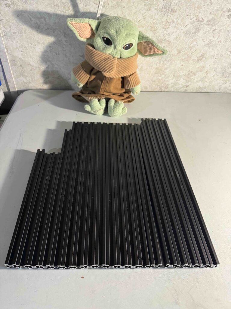
If you’re building a Voron-style printer, you can build your own 3D printer frame from raw aluminum extrusion.
In many builds, the frame shows up as a finished component — pre-cut, pre-drilled, and ready to assemble. That works well when frame kits are available and you’re building a standard configuration.
In our case, that isn’t an option.
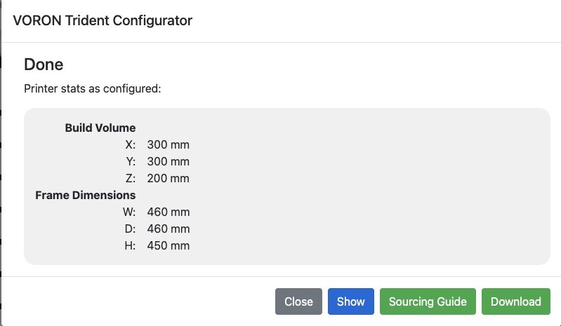
For this build, we are intentionally shortening the printer to increase frame stiffness. There is no off-the-shelf frame kit available in this size, so the only way forward is to fabricate the frame ourselves: ordering 2020 aluminum extrusion, cutting it to length, drilling access holes, tapping ends, and assembling the frame from raw stock.
This series documents how to do exactly that — starting with the most important step of all: understanding where the dimensions and machining requirements actually come from.
Interpreting Misumi Part Numbers in the Voron BOM
Read to the bottom for an example interpretation. Head over to the playlist for the HOW TO BUILD A PRINTER SERIES to get all of the videos.
One of the most confusing parts of building a printer frame from scratch is that the official Voron documentation does not usually provide explicit cut lists or drilling diagrams.
Instead, the information is encoded in the bill of materials, specifically in the Misumi extrusion part numbers.
At first glance, those part numbers look opaque. In reality, they contain everything you need to reproduce the exact same frame geometry — if you know how to read them.
Using our Trident-based build as an example (shown in the image above), each extrusion listed in the BOM communicates:
- The extrusion profile (2020)
- The exact finished length
- Whether the ends are tapped
- Which ends are tapped
- Whether blind corner access holes are required
- Where along the extrusion those holes are located
For example, a part number such as:
Misumi HFSB5-2020-420-TPW
Tells you that this is:
- A 2020 aluminum extrusion
- 420 mm long
- With both ends tapped
Other suffixes indicate:
- Single-end tapping
- Blind corner access holes
- Drilled features at specific distances from one end
When you interpret the BOM this way, it effectively becomes your cut list and machining guide. Voron does not spell this out step-by-step because most builders never need to — but if you’re fabricating your own frame, this is the key skill that makes everything else possible.
In the following videos, we take this decoded information and turn it into physical parts: cuts, drills, taps, and ultimately a complete, square frame.
Tradeoffs and Caveats of Building Your Own Frame
Building a printer frame from scratch is absolutely doable — but it comes with real tradeoffs that are worth understanding before you commit.
Tradeoffs
A properly manufactured frame kit is cut, drilled, and tapped with high accuracy and consistency. When you fabricate your own frame, you introduce the possibility of error at every step:
- A cut that is slightly out of square
- A length that is off by a fraction of a millimeter
- A tapped hole that isn’t perfectly aligned
These errors don’t always show up immediately. They often manifest later as difficult-to-diagnose issues:
- Frames that refuse to square cleanly
- Subtle binding in motion components
- Print artifacts that don’t respond to tuning because the underlying geometry isn’t true
There is also the practical reality that mistakes cost time. A bad cut or mis-drilled extrusion may need to be re-made, which means re-cutting material and repeating work you already did once.
None of this makes building your own frame a bad idea — it simply means accuracy and patience matter.
Caveats
One important detail that often surprises first-time builders is aluminum extrusion specification.
If you order extrusion directly, most suppliers will ship European-spec aluminum. In that case, the internal bore diameter at the ends of the extrusion is larger than what many Voron kits assume.
Practically, this means:
- You will often need to tap the ends to M6 instead of M5
- Blind corner fasteners will need to be M6 hardware
- This must be accounted for before you drill access holes
None of this is difficult, but it is something you must plan for. Mixing assumptions between kit hardware and raw extrusion can lead to frustrating fitment issues later in the build.
Frame Extrusions — What the Part Numbers Actually Mean
Misumi HFSB5-2020-450-LCP-RCP-AV310 (Qty: 4)
This part number describes:
- 2020 aluminum extrusion profile
- Finished length: 450 mm
- Blind corner access holes on both ends
- LCP = left-side access holes
- RCP = right-side access holes
- A drilled feature located 310 mm from one end (AV310)
In practice, this tells you:
- Cut the extrusion to 450 mm
- Drill blind corner access holes on both ends
- Drill the specified internal feature at the defined offset
Misumi HFSB5-2020-420-TPW (Qty: 9)
This part number describes:
- 2020 aluminum extrusion profile
- Finished length: 420 mm
- Tapped on both ends
In practice:
- Cut to 420 mm
- Tap both ends (thread size depends on extrusion spec, typically M5 or M6)
Misumi HFSB5-2020-420-AH210-TPW (Qty: 1)
This part number adds one additional feature:
- Finished length: 420 mm
- Both ends tapped
- A drilled hole located 210 mm from one end
This extrusion includes:
- End tapping on both sides
- A single drilled feature at a precise distance along the length
Misumi HFSB5-2020-420-AH210 (Qty: 1)
Similar to the above, but:
- No end tapping specified
- One drilled feature at 210 mm
This tells you:
- Cut to 420 mm
- Drill the feature at the specified offset
- End preparation depends on how it is used in the frame
Misumi HFSB5-2020-380 (Qty: 1)
Misumi HFSB5-2020-290 (Qty: 1)
These are the simplest entries:
- 2020 extrusion
- Finished lengths of 380 mm and 290 mm
- No additional machining specified
In practice:
- Cut to length
- All other operations are defined elsewhere in the assembly
Misumi HFSB5-2020-282-LTP (Qty: 1)
Misumi HFSB5-2020-280-LTP (Qty: 1)
These entries specify:
- Finished lengths: 282 mm and 280 mm
- Tapped on one end only
“LTP” indicates a single-end tap, with orientation defined by how the part is installed in the frame.
Why This Matters
When you break the BOM down this way, it becomes clear that the Voron documentation already contains all the information needed to fabricate a frame — it’s simply encoded rather than spelled out step-by-step.
Once you understand how to read these part numbers, you can:
- Build non-standard frame sizes
- Modify existing designs
- Fabricate replacement parts
- Work confidently without relying on pre-cut kits
The remainder of this video series takes these decoded requirements and turns them into physical operations: cutting, drilling, tapping, and assembling a square, rigid printer frame.